Saturday, December 17, 2016

Emergency Communications, Part 2, My VHF Jump Kit

This kit has been used at Field Day since about 2008. Additional photos can be seen here. The antenna is deployed in the front of the building and the kit is on the podium in the front of the room where our radios were set up.

I have also used this portable and when I take road trips.  It is quite handy and easy to use. The only addition I plan to make is a small 3 element beam and maybe an AR-270. 


VHF Jump Kit
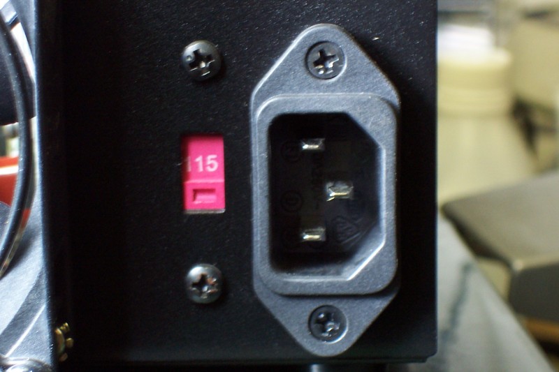
The kit consists of an Icom IC-2000H with a standard microphone, external speaker, ear buds, Mirage B-34-G all-mode VHF amp, and Icom IC-u2AT handi-talkies. The kit is powered by an Astron SS-30 power supply. The kit is able to be operated from 120 volt a.c. mains power or a generator or a 12 volt battery.


The antenna is an Evans Engineering EE-3 along with a Hustler CG- 144 with the radial kit which I deploy with the mast made from a Lowe's 14 foot pool cleaning pole. I got interested in the EE-3 antenna after reading an article in QST magazine. I thought about building one, but the cost was so close with buying antennas and making the hardware that it was easier to just buy one. Similarly with the Hustler radial kit. I could have gotten some stainless steel or aluminum rod and made my own, but not having any in my junk pile I opted to just spend the fifteen or twenty dollars and buy one. I have a nice magnet mount antenna (5/8 wavelenght) to round out the kit. For my HT I have the MFJ magnet mount and the Diamond triband SRH320. Diamond also makes a nice small mag mount for the antenna.
Note from a post on another site: The EE-3 site no longer exists. Perhaps Bob is no longer making the antenna.
There are several other sites on the web for building go-kits among them the Salvation Army http://www.satern.org/,
KB1DIG's site http://home.comcast.net/~buck0/hamgear.htm , W2IK, Robert Hejl had a great amount of portable and emergency operation information on his site before aol zapped GeoCities. I have not been able to find the archive, and Prince William County Virgina http://www.pwcares.org/
Here is a link to one of the first sites I used when deciding what kind of a kit to build http://home.comcast.net/~buck0/combox.htm Scroll about 1/2 way down the page and you will find the Salvation Army orange boxes. There are plenty of links to follow on this page including a link to the step-by-step article by N0VLR on building the HVOB- Highly Versatile Orange Box (link to the PDF is below the HF jump kit at the bottom of this page).
That is a start on some sites I used and still use. Search the web. There are many many sites for go-kits and emcomm.
My search for a suitable case started with military surplus, but found nothing I liked. Next was to build one out of plywood. That too was dismissed due to the amount of work I did not want to do and the weight. I thought of combining HF and VHF, but that limits both kits to some extent and again gets to be rather large and heavy for the gear I have that I want to use.

 
On a trip to a local Gander Mountain store I found a suitable MTM Case-Guard box. http://www.mtmcase-gard.com/ Gander Mountain has a site, but the site is not very useful. I chose the SPUD2-11 since the inside dimensions were almost what I needed and will allow me to exchange the IC-2000 with a dual band rig if I choose. I have a SPUD-7 for HF.


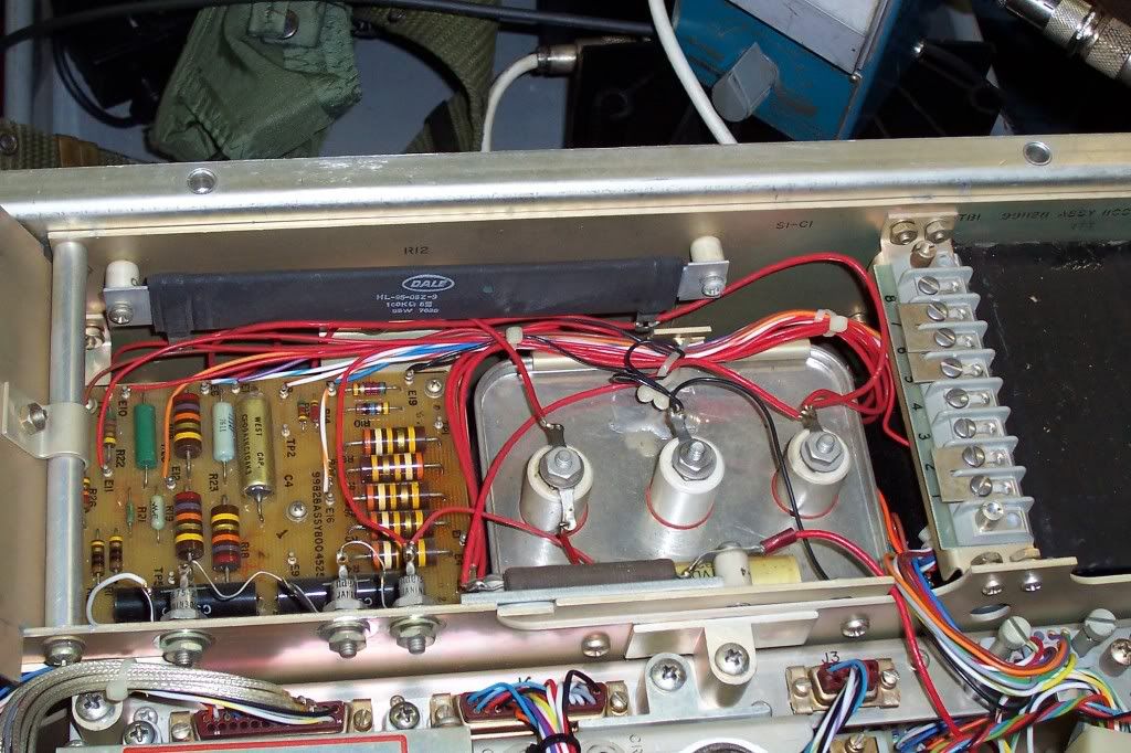
I started by adding some Anderson Power Pole connectors to the power supply. I got the idea from this site http://www.repeater-builder.com/astron/ss30-powerpoles.html while searching on information on something else. I like using what I have rather than buying it, and I like using methods developed by others when they can make my job easier. When I worked for a major connector manufacturer it was called adapting and using Best Demonstrated Practices. Like some of the things from the fire service this is something that rubbed off on me from industry.


Next I started to lay out and install the equipment.
 
There was a problem with the smaller case and the D.C. supply. The power cord had to have a 90 degree IEC connector; in the wrong direction. I turned the connector on the power supply.


As I changed it
 
Then it was off to the scrap pile and find a piece of metal to mount everything. Wood would use too much space or not be as strong. Besides I wanted to be able to clip to anything anywhere to ground the box. To mount the power supply I just replaced the screws that hold the feet onto the case with longer 2mm machine screws so I did not need to drill the case.
The amplifier was attached using holes already in its case.
 
The IC-2000H was mounted to another plate which would mount to the top of the dry box with 10-32 rack screws. I mounted the rig with L-brackets rather than the mobile mount for a more compact mount.
 

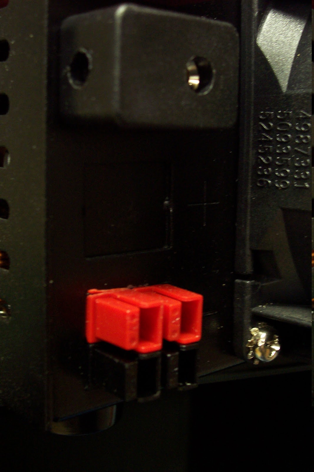
Dual banana plugs for D.C. power. I chose this method rather than a solid state or relay change-over switch or relay. I use a spare U.P.S. for a power line filter/conditioner/buffer when on mains power or a generator. This is a good ideas since spikes, sags and other things can happen during a disaster and ruin your power supply and / or rig. Having an un-interruptable source also will allow the time needed to connect the battery input and remove the jumpers linking the kits supply from the external battery input. If the dual banana plugs making the links get lost, using the binding post style of banana jack allows me to wrap wire, tin foil or anything conductive I can find across the link to use the internal power supply. So what if the foil or something else may not be as efficient as 12 or 14 a.w.g. copper, it works. Under normal circumstances I can hit most repeaters in our area with 0.10W. Almost always 100% quieting with 1 watt. If I need the entire full power (50W) of the IC-2000 or the full 30 to 35 watts from the amp it would only be if all the repeaters in our county and the neighboring counties are destroyed However, you may be in a region where the full power is needed...so do not short change your self by relying only on a hand held. Besides what if simplex is required?

 A fan that is about one inch from the back wall or bottom of the dry box. The fan is positioned to blow air across the rig (and into my face), but it is only a 3 inch 12 V.D.C. fan that will only run if the power supply is used.


A male chassis mount 120 v.a.c. IEC connector was also mounted in the center of the back (bottom) to connect mains power to the Astron. The power supply output is connected to the top set of banana jacks and all the D.C. power feeds to the equipment is from the bottom set. I made 2 spare cables terminated in Anderson Powerpole connectors for any auxiliary need including a hand held. I fold the extra cable back and forth on itself between the PSu and amp and the amp and case similar to the way attack lines are cross laid on a fire engine. The one on the right is from the Astron. The one on the left is from the D.C. input banana jacks.


The RF connectors are all on the same side of the box as D.C. power, and everything gets labelled.

 
Here is the completed kit .
The ear buds are some of my favorite. Less than a dollar at Wal-Mart When the kit was built in 2007 and are neraly $3.00 now and have a shorter cord. They work fine with my Rockmite, MFJ code generator, and even my MP3 player.
Also included in the kit is a Leatherman tool, RF adapters, some RF patch cords, PowerPole patch cords, a 2 AA cell mini mag light* converted to LED, gaffer's and duct tape, RG-213, the mast and a few other items I know I forgot to mention -- like rechargeable batteries. The kit weighs 23 pounds as seen.
Since the original post Wal-Mart quit selling decent ear buds under $15 or $20. I do not recall if they sell any under those prices. I since get all of mine at the Dollar Tree store. Great sounding ear buds in several styles for $1.00.

Not shown for the VHF kit is a short ethernet cable jumper to keep the strain off of the asinine RJ-45 connector used for the microphone. I replaced the jack twice on this rig and hope to avoid a third time by using a jumper. Whoever the engineer who designed and manager who approved the use an RJ-45 for a microphone connector should get the JackAss of all time award! These connectors give problems when installed where they do not get nearly the strain of using them on a mobile or any other radio.


*Rather than an expensive light, Harbor Freight sells 2 nice 9 L.E.D. flashlights with batteries in a 2-pack for $3.00 on sale. The regular price for one light alone is around $5.00. Look for Harbor Freight ads in the newspaper. The LED flashlight is often offered FREE.


This post is laid out a bit different than it appeared on my web site. It was easier to repost it here than try and do it on my site.  Besides by 2017 the site as it has been will be gone, I may decide to use a different host service, but that all depends on how much I like using Blogger.here will be more on VHF in Part 3.


Friday, December 16, 2016

Emergency Communications, Part 1

Originally posted on by web site as a single long page it is too much to post all at one time on Blogger.  As done with the mast information it'll be done in parts.

I also edited the original post from 2010.  The edits are in green to avoid confusion with links. 
Blogger there is a problem.  Blogger renders the blue link text as red.  I did not re-edit the original.  Pleas pardon the crappy green.

From my web site:

Welcome to my emergency communication (EmComm) page.
Part of Emergency Communications is Emergency Preparedness. Be prepared, always prepared. There are many sites related to emergency preparedness, but few ham sites cross over and few of the others mention ham radio. One of the things is to always have first aid training and supplies in the house and every vehicle. What supplies may depend on ones amount of training. Also at least one fire extinguisher in the house, garage, and each car.  Each communicator should be trained in basic and even advanced first aid, CPR, and fire suppression. Many A.R.E.S and RACES groups require several FEMA classes and even the ARRL Emergency Communications courses. All are topics requiring more space than can be handled on this site.
In Florida we not only get hurricanes we also get wild fires and search and rescue deployments. We've got an active A.R.E.S. group here in Flagler County, www.flaglerares.org, and Flagler County Emergency Communications Association http://www.flagleremcomm.org as well as REACT http://www.react4800.org. Flagler County Emergency Communications Association and members maintain several repeaters throughout the county. The 2-meter band is used as the primary emergency band as well as 70 cm, D-Star and GMRS. For those interested in D-Star and more information on some of the ham radio activities in Flagler County please visit the Noth East Florida D-Star repeater blog at NE-FL D-STAR
This page was copied from the original web site. The ARES link may or may not work as Flagler ARES has changed sites several times since this was originally posted. The D-star group is also not as active as it was at first so the link may or may not be current.
Several amateur radio operators in Flagler County belong to all of the above listed organizations as well as being emergency volunteers for the County EOC and the local fire departments. Many also belong to the Flagler Palm Coast Amateur Radio Club. Information on this club can be found here: W4FPC.
Please visit the above sites (or Facebook) for more information on our repeaters and if you live in or near Flagler county and are interested in getting your amateur radio license please contact one of our members for information on licensing. The sites also contain emergency information. The county emergency site is http://www.flagleremergency.com/
To be prepared for an emergency deployment I decided like many hams to build a jump kit or go-kit. These kits can be as simple or complicated as desired. My first kit was made from an ammo can which held a gel battery and VHF amp to power my HT. As things progressed I decided to get with the program and build a bigger kit that I could use at home, on the road, or for emergency communication. I've seen kits built from file carriers, large ammo cans, tool boxes, tube caddies, wooden boxes and even the $7.00 orange box from Wal-Mart that now costs about $18.00 (find them in the marine section in sporting goods). File carrier boxes can be bought for less than $10.00 or choose the more expensive ones.  As far as the emphasis placed on water proof by some, water proof is not necessary. Will the station be operated under water? It it nice to have a case that keeps the rain water out during transport, but unless all connectors are sealed, all screws and other mounting hardware that goes through the case is sealed, a water proof case will no longer be water proof. I used o-rings between the connector flanges between the case and around the connectors, silicon seal in the screw holes, but I do not think I would like to subject my kit to being submerged. My cases are made by MTM-CaseGuard and all state -- water resistant, not submersible, NOT waterproof.

Thursday, December 15, 2016

1080-00-108-1173 Camouflage Screen Support System Masts


Those of your who have read my former web site and blog posts may recognize the following paragraph:


The Cape Cod Packet Group had good information on these masts, guying information, and deployment. They use one 1080 mast set for a G5RV in an inverted V configuration. There was also a link on the site to another guy ring design. If deploying a G5RV in this manner 2, 10 ft. or longer crappie poles can be installed at the ends to keep the ends out of reach or ropes may be affixed to the ends and stretched out to anchors to keep the ends safely out or reach. Anyone know what happened to the CCPG or their site?


The CCPG still has a site, but the mast information is not there.
I was searching on the NSN and found the original web page HERE!
I hope the link works. This page shows the G5RV configuration I have been using with the

1080-00-108-1173 Camouflage Screen Support System Masts and my AB155-A/U mast using the tripod adapter.


Finally, if you want to compute the minimum guy length use the Pythagorean theorem: one side of the right triangle formed by the mast and the other is the ground. Determine how high you will make your mast. This is side a of the triangle. Then measure the distance from the mast base to the guy anchor. This is the other leg of the right triangle, side b. The guy is the hypotenuse, c. The advent of calculators made this really simple. Remember doing square roots long hand or with a slide rule? The theorem states side a squared plus side b squared equals side c squared, but we are interested in the length of c -- not the square.  This requires taking the square root of the sum of the squares of a and b.

Now you know the height of your mast and you know where you want the base and how far away you will place the guy anchor from the base. All anchors will be equally spaced from the base.

For example, 50 ft to the top of the mast, 35 ft from the base to the anchor. This will be the length of the top set of guy ropes.

Square each distance: 50 squared is 2500. 35 squared is 1255.

Add the two squares (2500 + 1255) = 3725. This is the square of the hypotenuse.

The guy is the hypotenuse of the right triangle. To get the answer for the length, take the square root of the sum of the squares which equals 61.033 feet.

Now add how much extra you will need to fasten the rope to the mast and to the anchor.

I use spring clips at the mast ends of the guys fastened with a bowline knot. For this I allow one foot. At the anchor end I use a Taunt-line hitch or other sliding knot that will bind and not slip under tension. (see my post from 9 December 2016, Military Masts, Part 2)  I allow anywhere from 3 to 5 feet extra at this end. My total length would be 65 to 67 feet. Many times I use more depending on how many guy lines I get from a spool of rope.

Do this for each set of guys.  For example for a 44.5 foot mast using 12 sections (44.5 inches long each) of the  1080-00-108-1173 masts the bottom guys would be 4 sections high or 14.83 feet, the middle ones 8 sections high or 29.33 feet, and the top would be 12 sections high or 44.5 feet.  It is much easier thinking 4 foot per section than the odd feet and inches so I use 16 feet, 32 feet, and 48 feet.

Each section is 44.5 inches to 44.625 inches long when assembled.  The multiples are repeating decimals that never end.  Rounding to 2 places is good enough.  Using 48 inches or 4 feet as the length of each section of calculations makes calculating the lengths much easier.

If you doubt your math, lay out a mast on the ground, measure (or mark) heights and the base to anchor distance, and use a 100 meter/330 foot tape from Harbor Freight to measure the distance from where you want to place your guys on the mast to the anchor point.

This could even be done on an empty parking (if you have permission to use the lot) lot using chalk, but you need to be certain that the distance from the top to the bottom of your chalk line mast is straight and the distance from your chalk line mast base to the anchor point is a square angle (90 degree angle).  Do one side of the mast.  Then you know how much rope you need for one set.  Multiply the total of this set by how many guys you want to make.

Wednesday, December 14, 2016

FAA Amplfier AM-6154


A few years ago I bought some FAA amplifiers to repair and put on the air with the intention of placing one in service at a repeater site and using one on my TS-700A.  This is the first amplifier of the project.  There are many sites and pages posted on the web for modifying these amplifiers.  Most of that information will not be restated here.
This was the first amp that was put on the air.  It required only a few repairs to use it on 2 meter FM.  The first thing I do when working on an amplifier is disconnect it from the power line and short the plate supply to ground.  The metering resistors (R1 &R2) in the H.V. supply were changed to 3 watt non inductive 2%.  See the 2nd and 3rd photos.  Then the bias was modified to allow full cut-off at idle and correct drive when keyed.  The filter and directional coupler were removed since they will not take the power created on the ham bands.  Nothing else was changed in the cavity.  Not making any mods in the grid circuit of the cavity will make input tuning very sharp which is what I wanted for repeater duty.  If garbage cannot make it through the input it can't be on the output. 
The next change was to add the keying relay.

The wiring was done through the rear connector and D connector (J4) for the grid supply. I chose this method since the FAA had a zero idle current mod. for the amp that used the same wiring in the D connector and key input on the exciter connector.  I did not use the ECG-123A and photocoupler circuit.  I added a vacuum relay mounted to the back panel that holds bias at cut-off when not keyed and allows full plate current when keyed.  Reverse polarity is protected by a diode and the relay contacts protected by a 10k resistor mounted on the grid supply.  Thermal protection for the cavity originally is provided by power from the exciter.  I mounted a separate DC supply to power the circuits for cooling.


 This view is the high voltage supply showing the 2, 10 ohm resistors (R1 & R2) that get replaced.  They are the 2, 1/2 watt resistors in the lower left corner of the circuit board.  Be careful to safety the capacitor before doing any work.  Also note the strapping of the TB.  It should be set to the line voltage you intend to use to power the amp.  The TB on the grid supply also needs to be strapped to the correct line voltage. The close-up shows the new resistors installed.
 The cover of the H.V. supply must be removed and the board removed from the stand-offs to change the resistors.  The power supply does not need removed.  I jumper the capacitor to ground as soon as I lift the cover and before starting any work.  
This is a close-up view of the new resistors.  I used ambient light for this so it is a bit dim.
The original Eimac 8930 tubes are getting quite scarce and expensive I made a reducing ring to use 4CX250B tubes.
Here is the cavity converted to use a 4CX250B.
 
 Here is a copy of 22 pages of the manual.  Note that tuning states using the TUNE function of the amp.  This will not work since the directional coupler and filter are removed to use the amp on the ham bands. This is about 15Mb so it may take awhile to load.     Link to Manual

N1RWY had (according to posts on the internet) a great site about these amps.  However no one knows what happened to N1RWY or the site.  If any one has any information please email. The call is still in the FCC database, but any email addresses bounce.  I found an archive to his site and here is the link to the amplifier section:     http://web.archive.org/web/20071014044729/n1rwy.com/am6155/index.html
Please wait until the page loads for the link to the archive.  When I created the link it pointed to the correct page and for some reason it now opens with a reidirect page from the archive.  The correct archive will load.  There are several archives for the AM-6154 repository and I will locate and post the correct direct link (probably after Field Day 2011)
 There is a history of the amplifier and many other notes there. Courtesy of the Wayback Machine.  Sometimes this link opens directly and some times to a page stating that the archive is opening to the closest date.  There are several archives of this site and the only thing I can tell is one does not have the history of the AM-6154 page.
The Waback Machine web pages have changed over time and the original archived pages are not the same as they presently display.
This was copied from my site.  Hopefully the links are not dead.  The arrangement is not exactly as planned.  Some of the photos shifted and alignment is not how it originally displayed.