
This was the first amp that was put on the air. It required only a few repairs to use it on 2 meter FM. The first thing I do when working on an amplifier is disconnect it from the power line and short the plate supply to ground. The metering resistors (R1 &R2) in the H.V. supply were changed to 3 watt non inductive 2%. See the 2nd and 3rd photos. Then the bias was modified to allow full cut-off at idle and correct drive when keyed. The filter and directional coupler were removed since they will not take the power created on the ham bands. Nothing else was changed in the cavity. Not making any mods in the grid circuit of the cavity will make input tuning very sharp which is what I wanted for repeater duty. If garbage cannot make it through the input it can't be on the output.
The next change was to add the keying relay.

The wiring was done through the rear connector and D connector (J4) for the grid supply. I chose this method since the FAA had a zero idle current mod. for the amp that used the same wiring in the D connector and key input on the exciter connector. I did not use the ECG-123A and photocoupler circuit. I added a vacuum relay mounted to the back panel that holds bias at cut-off when not keyed and allows full plate current when keyed. Reverse polarity is protected by a diode and the relay contacts protected by a 10k resistor mounted on the grid supply. Thermal protection for the cavity originally is provided by power from the exciter. I mounted a separate DC supply to power the circuits for cooling.
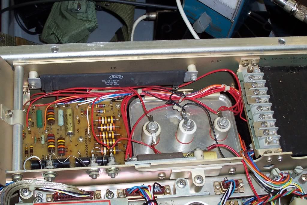
This view is the high voltage supply showing the 2, 10 ohm resistors (R1 & R2) that get replaced. They are the 2, 1/2 watt resistors in the lower left corner of the circuit board. Be careful to safety the capacitor before doing any work. Also note the strapping of the TB. It should be set to the line voltage you intend to use to power the amp. The TB on the grid supply also needs to be strapped to the correct line voltage. The close-up shows the new resistors installed.
The cover of the H.V. supply must be removed and the board removed from the stand-offs to change the resistors. The power supply does not need removed. I jumper the capacitor to ground as soon as I lift the cover and before starting any work.

This
is a close-up view of the new resistors. I used ambient light
for this so it is a bit dim.
The original Eimac 8930 tubes are getting quite
scarce and expensive I made a reducing ring to use 4CX250B tubes.
Here is the cavity converted to use a 4CX250B.

Here is a copy of 22 pages of the manual. Note that tuning states using the TUNE function of the amp. This will not work since the directional coupler and filter are removed to use the amp on the ham bands. This is about 15Mb so it may take awhile to load. Link to Manual
N1RWY had (according to posts on the internet) a
great site about these amps. However no one knows what happened
to N1RWY or the site. If any one has any information please
email. The call is still in the FCC database, but any email addresses
bounce. I found an archive to his site and here is the link to
the amplifier section:
http://web.archive.org/web/20071014044729/n1rwy.com/am6155/index.html
Please wait until the page loads for the link to the
archive. When I created the link it pointed to the correct page
and for some reason it now opens with a reidirect page from the
archive. The correct archive will load. There are several
archives for the AM-6154 repository and I will locate and post the
correct direct link (probably after Field Day 2011)
There is a history of the amplifier and many
other notes there. Courtesy of the Wayback Machine. Sometimes
this link opens directly and some times to a page stating that the
archive is opening to the closest date. There are several
archives of this site and the only thing I can tell is one does not
have the history of the AM-6154 page.
The Waback Machine web pages have changed over time and the original archived pages are not the same as they presently display.
This was copied from my site. Hopefully the links are not dead. The arrangement is not exactly as planned. Some of the photos shifted and alignment is not how it originally displayed.
the info from the n1rwy.com site was lost, now found and moved to http://www.n1rwy.org/am6155
ReplyDeleteJay,
ReplyDeleteThanks for the link. One of the most frequent email requests is for information from N1RWY's site. There is a VHF group that liked his site also.
No worries, I am working on updating the site to move it to a wordpress format like my blog. The layout of the AM6155 info is very static html code and not up to speed with 2017 standards! - Jay (N1RWY)
Delete